Configuring the hardware
Connect the MR-ESC-AM32 to an AM32-supported flight controller — signal pin to the motor pin on the flight controller.
Connect a battery (2S–6S) or PSU to the input connections and enable power.
Connect the flight controller to the PC via a USB cable.
Open the online AM32 configurator and connect to the flight controller.
Adjust the settings according to the motor requirements.
Save the settings, disconnect the flight controller, and reboot the MR-ESC-AM32.
Set up the flight controller to control the MR-ESC-AM32.
Note: Only one ESC can be configured at a time, and it must be connected to AUX1. The AM32 configurator can show up to four ESCs per vehicle, but only the ESC on AUX1 is read.
Setting up the ESC with the RT1176 VMU
Note: ArduPilot, Betaflight, and CogniPilot software on flight controllers can program and configure AM32 ESCs using their default passthrough programming support. This section is only needed when using a PX4-based MR-VMU-RT1176 because, at the time this document was published, PX4 did not support AM32 programming. PX4 may add AM32 programming support in the future.
Caution: Flashing the MR-VMU-RT1176 with ESC passthrough firmware will overwrite the existing PX4 software and configuration. Before proceeding, make sure the procedure to restore the bootloader and reinstall the desired PX4 version on the flight controller is understood. Restoring PX4 is beyond the scope of this document. Review the MR-VMU-RT1176 documentation and confirm the recovery process is understood before continuing.
This section assumes using an MR-VMU-RT1176 programmed with Zephyr RTOS-based ESC passthrough software.
If the MR-VMU-RT1176 has not been programmed for ESC passthrough, complete these steps:
Connect the VMU to the PC using USB-C to supply power. Connect the 10-pin Pixhawk Debug Full connector to the debugger, using either MCU-Link-MR or J-Link with a Pixhawk adapter board.
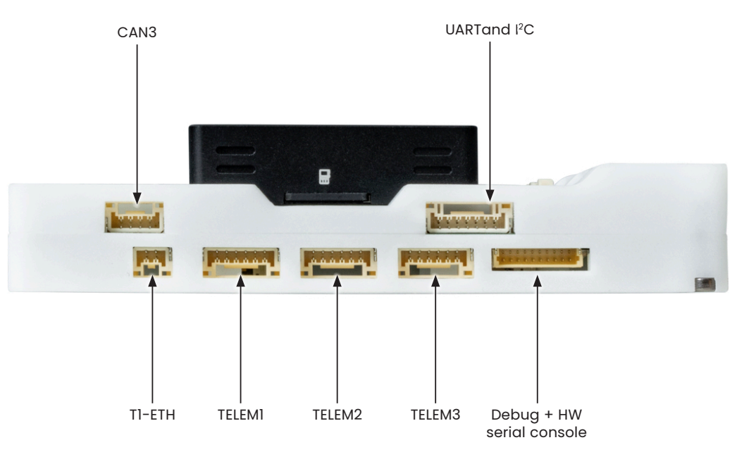
MR-VMU-RT1176 connectors
Flash the ESC passthrough firmware:
If using a J-Link debugger:
For Windows: execute
JLink_VMU_ESC_passthrough_flasher.batFor Linux: make
JLink_VMU_ESC_passthrough_flasher.shexecutable and run it:chmod +x JLink_VMU_ESC_passthrough_flasher.sh ./JLink_VMU_ESC_passthrough_flasher.sh
If using an MCU-Link-MR debugger:
For Windows: execute
MCU_Link_VMU_ESC_passthrough_flasher.batFor Linux: make
MCU_Link_VMU_ESC_passthrough_flasher.shexecutable and run it:chmod +x MCU_Link_VMU_ESC_passthrough_flasher.sh ./MCU_Link_VMU_ESC_passthrough_flasher.sh
Follow the instructions shown when the flasher runs to flash the VMU.
Disconnect and reconnect the USB-C cable to power-cycle the VMU.
Connect the ESC PWM input connector to the VMU, ensuring that the signal and ground are correctly oriented as shown below.
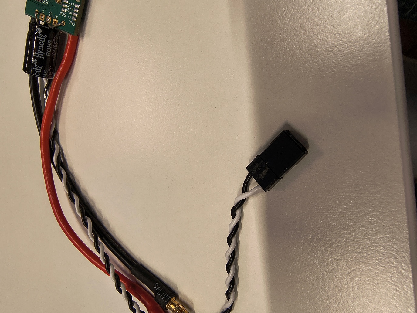
RC PWM connector signal and ground
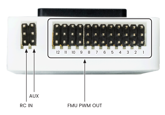
MR-VMU-RT1176 PWM out pins
Working on target
Running the MCXA133 ESC application is a three-step process: write the application(s), configure the ESC, and connect the ESC to a flight controller or RC receiver.
1. Writing the application
Using a Segger J-Link or an NXP MCU-Link-MR(PRO) debugger, flash the main application image (for example AM32_FRDM_A153_2.20.hex) into the MCXA133 flash.
Note: The NXP MCU-Link-MR hardware interface with the ESC uses a different cable from the J-Link one. Although the connectors are identical, NXP requires pin 3 to not be connected — see the image below.
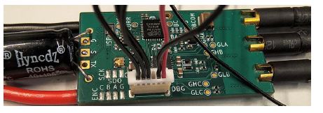
MCU-Link debug connector with pin 3 removed
For J-Link, execute:
JLink.exe -CommanderScript temp.jlink
The temp.jlink script can be created on the fly from a batch file, for example:
(
echo device MCXA133
echo si SWD
echo speed 4000
echo connect
echo r
echo h
echo erase
echo loadfile C:\NXP\AM_ESC\NXP_ESC_AM32_Programming\AM32_FRDM_A153_2.20.hex
echo r
echo g
echo exit
) > temp.jlink
For MCU-Link-MR/PRO, execute:
LinkServer.exe flash MCXA133 load "C:\NXP\AM_ESC\NXP_ESC_AM32_Programming\AM32_FRDM_A153_2.20.hex"
On a blank device it is mandatory to also load the AM32 bootloader together with the main AM32 firmware. The bootloader is loaded with the same operations described above.
2. Configuring the ESC
ESCs require calibration and configuration to match the hardware specifications of both the motor and the flight controller / RC receiver. Calibration of the AM32 ESC is done with the help of a flight controller flashed to run in passthrough mode, which allows the ESC to be connected to a USB/serial port on a PC. Configuration is done via the web-based AM32 configurator or with a Windows-based serial tool.
Note: After flashing a new image, an error may appear if the entire flash was erased during programming. To fix this, load the default configuration and save it to flash. Then set the other parameters as required — for example, the KV parameter should be set close to 960 (based on the motor characteristics), and the input signal can be either DShot or PWM depending on how the ESC is connected (directly to an RC receiver or via a flight controller).
3. Connecting the ESC to a flight controller or remote-control receiver
When connecting the ESC via a flight controller or RC receiver, ensure that the signal coming out of the controller/receiver matches the configuration of the ESC. QGroundControl can be used to configure the flight controller to send the signal to the ESC using either PWM or DShot. For a direct connection to an RC receiver, this configuration is done in the remote-control transmitter unit.
Note: Pay attention to the polarity of the connector pins when switching between the RT1176 VMU and an RC receiver unit. The i.MX RT1176 VMU connectors have the GND pin on the top side, while the receiver may have it on the bottom side.