Board components and connectors
This chapter identifies the board connectors and featured components. For the functional-block description of the hardware (power stage, gate driver, BEMF network, and so on), see the Hardware Architecture and Reference Design application note.
Kit featured components
The following figure identifies the important connectors on the board.
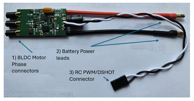
MR-ESC-AM32 board connectors
Number |
Description |
|---|---|
1 |
BLDC motor phase — 3.5 mm bullet female connectors |
2 |
Battery power leads — 3.5 mm bullet male (2) |
3 |
Dupont-style 3-pin RC-PWM/DSHOT connector |
The table below provides additional detail on the board interfaces.
Part identifier |
Connector type |
Description |
|---|---|---|
Motor phase A |
3.5 mm bullet connector |
Motor phase A |
Motor phase B |
3.5 mm bullet connector |
Motor phase B |
Motor phase C |
3.5 mm bullet connector |
Motor phase C |
Debug |
JST-GH 6-pin |
SWD debug connector (modified Pixhawk Debug Mini) |
VBAT+ |
Red wire / solder pad |
Battery + (2S–6S) |
VBAT- |
Black wire / solder pad |
Battery - |
G |
3-pin Dupont / black |
GND |
S |
3-pin Dupont / white |
Signal pin used for RC-PWM, DShot, BDShot, and configurator |
TX |
Solder pad |
UART telemetry data |
RGB LED |
Solder pads |
Addressable LED solder pads |
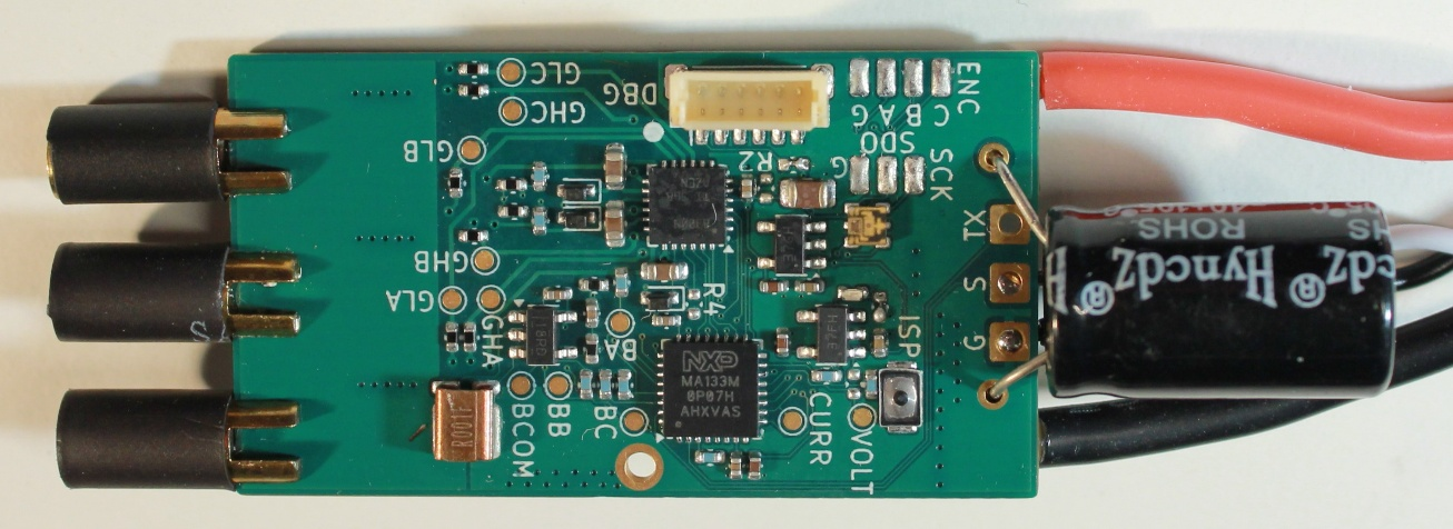
MR-ESC-AM32 board featured components
LEDs
The board includes one onboard RGB addressable LED at U5. It can be used to indicate vehicle status or orientation, depending on how the flight-control software uses the AM32 LED-control API. Additional individually addressable RGB LEDs can be connected to the expansion pads to support linear patterns or LED arrays. U5 is an American Bright BB-2020BGR-TRB LED that uses APA102/SK9822-style programming.
Switches
The board includes one switch labeled ISP. It connects to MCXA133 GPIO P3_29 and is not currently used by the AM32 software.
Schematic, board layout, and bill of materials
The schematic, board layout, and bill of materials for the MR-ESC-AM32 board are available on the NXP product page.